CIRCOM in zkProver
Although CIRCOM is mainly used to convert a STARK proof into its respective Arithmetic circuit, it is implemented in varied ways within the zkProver, specifical
Although CIRCOM is mainly used to convert a STARK proof into its respective Arithmetic circuit, it is implemented in varied ways within the zkProver, specifically during the STARK recursion process.
This document gives further elaboration on the Proving architecture by focusing on the CIRCOM Arithmetic circuits, while highlighting CIRCOM's pivotal role in the STARK Recursion process.
zkEVM batch prover
The first step in proving computational integrity starts with the zkEVM batch prover.
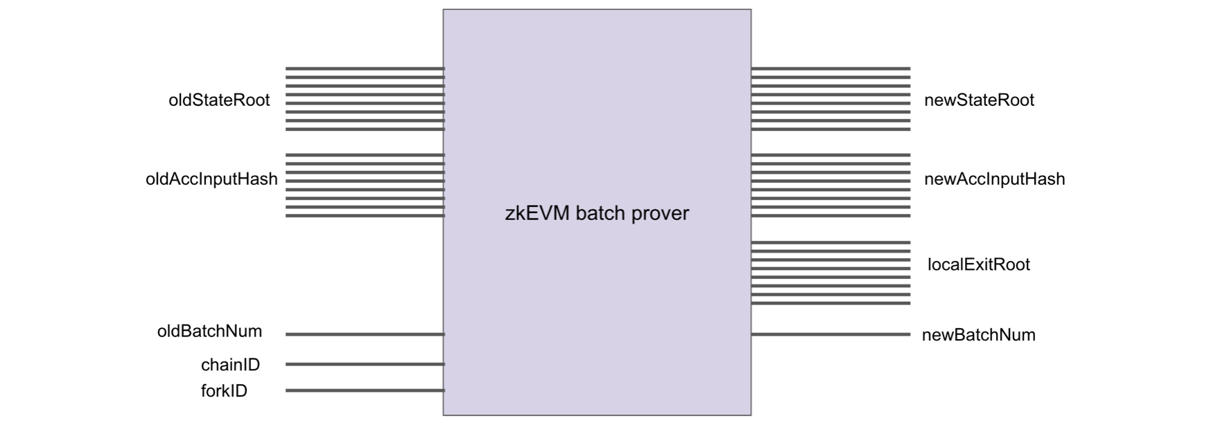
It is a circuit that proves correctness of the state transition from an oldStateRoot to a newStateRoot.
The zkEVM batch prover takes as inputs; the oldStateRoot, oldAccInputHash, oldBatchNum, chainID and forkID. And its outputs are; the newStateRoot, newAccInputHash, localExitRoot, and newBatchNum,

The localExitRoot is the Merkle root of the ExitTree used in the bridge to transfer information from the L2 to the Ethereum L1.
The oldBatchNum indicates which batch is being processed, and in each transition the numbering increments by , such that newBatchNum = oldBatchNum + 1.
All transactions being processed are encoded into the batch via the oldAccInputHash, read "old accumulated input hash".
Although built in a smart contract, the encoding of transactions resembles a blockchain, where transactions are chained together with the Keccak hash function. See figure below depicting this encoding.

The main idea, when proving validity of a batch, is for the oldAccInputHash and its corresponding newAccInputHash to match accordingly.
The resultant STARK proof denoted by , which involves committed polynomials each of degree , is Megabytes big.
Such a validity proof is not ideal in view of its storage cost in Ethereum.
The Polygon zkEVM's strategy to reducing the size of the ultimate validity proof is by implementing a recursive aggregation of many batch proofs into one.
CIRCOM circuits
As outlined in the Proving architecture subsection, the recursive aggregation of many STARK proofs (aimed at reducing the size of the validity proof) is accomplished in five stages;
- Compression stage using the c12a CIRCOM circuit,
- Normalization stage using the CIRCOM template,
- Aggregation stage using the CIRCOM template,
- Final stage using the CIRCOM template,
- SNARK stage using the CIRCOM template.
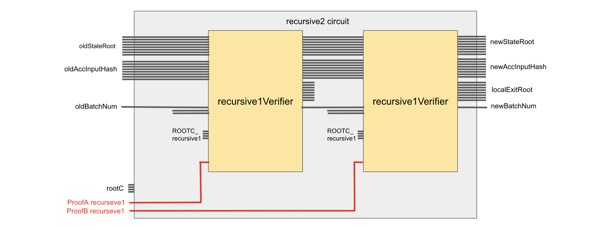
In terms of code, the three CIRCOM templates used in the middle stages (Normalization stage, Aggregation stage and Final stage) are identical except for their public inputs which are; the root constants RootC and the respective input proofs.
As previously mentioned,
- The only takes -type proofs as input,
- The only takes any pair of -type or -type proofs as input,
- The only takes a pair of -type proofs as input.
Since the underlying proof scheme is PIL-STARK, there is a built-in CIRCOM circuit in each of these prover circuits. Therefore, for any index , the proof output by any of the , is in fact a verified proof because PIL-STARK automatically verifies it.
A typical CIRCOM template, for any , looks like the circuit shown below.

Proof-size reductions
The below table displays reduction in proof sizes as one progresses from one stage of the STARK recursion to the next.
The numbers presented below were first publicised by the Polygon zkEVM Technical Lead, Jordi Baylina, during the StarkWare Sessions held in February 2023. The video recording can be found here.
Last updated on
Proving architecture
Focusing specifically on the proving phase of the recursion process; it is a process that starts with proofs of batches (these are sequenced batches of transact
Proving setup phase
All preprocessing happens in the Setup phase. This means all artifacts needed for generating proofs are created in this phase. This includes the generation of i